PowerPC JTAG Recovery (ICX6610)
This is a brief guide to recover corrupt bootloaders on PowerPC 85xx switches (ICX6610 or FCX) using a BDI2000.
Preparation
Start by downloading this ZIP.
Put all the files from the zip into the root of your TFTP server - the JTAG unit has been preprogrammed to look for a TFTP server at the address you specified before the unit was shipped - make sure said TFTP server is running with above files before powering the BDI2000.
Note: If you are attempting this with your own BDI2000 and need the appropriate MPC85xx BDI firmware, contact me via GitHub or STH.
If the TFTP server is running on linux, you need to create an empty file in the TFTP root called badboot.bin - and give it write permission by running CHMOD 777 badboot.bin - this allows the JTAG unit to write to this file. if you are using a windows TFTP server, this shouldn't be necessary.
Connections
If you are outside the US, please plug the power brick into the wall first WITHOUT CONNECTING IT TO THE BDI2000! This is to test the power adapter, if it blows up from 220 volts, it won't take the BDI2000 with it.
If you plug it into the wall and nothing happens (it shouldn't), unplug it from the wall. Now plug your ethernet cable into the BDI2000 (which should still be powered off).
Now plug in the power supply to the BDI2000. Be gentle and make sure the key on the plug is facing the correct way - I had to hack up that power supply out of parts as it did not come with one.
Once you are sure it is plugged in correctly, and it is also connected to your network via ethernet, plug the power brick into an outlet - the BDI2000 should power up.
Using a telnet capable program like putty, telnet to the BDI2000 unit - it has been preconfigured with the IP you specified before shipping - You should get output like the below, saying it's waiting for a target:
TARGET: waiting for target Vcc
TARGET: waiting for target Vcc
TARGET: waiting for target Vcc
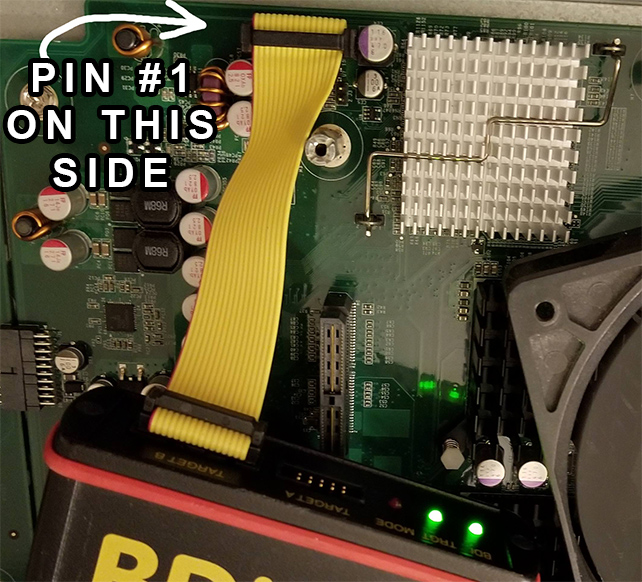
Now you must connect the BDI2000 to the ICX6610. Make sure the switch is unplugged and powered off! Find the 16-pin JTAG header on the switch. On the JTAG header, 1 should be printed on one side of the header to indicate pin number 1. Find which side of the header that 1 is on.
Plug in the cable so pin #1 is on the left side, like this:
On an ICX6610, the connection should look like this:
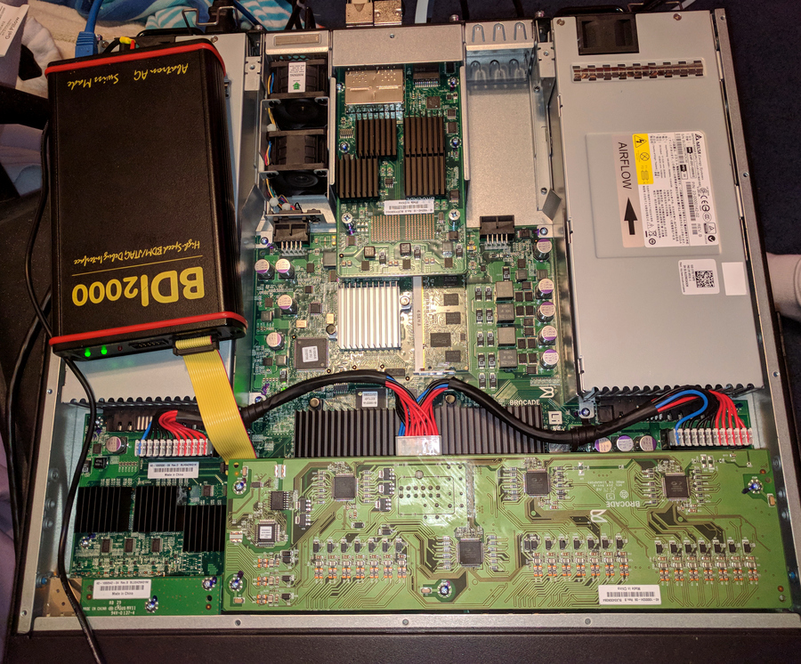
Note: The above picture is a 48 port ICX6610. The 24 port ICX6610 will have a slightly different board layout, and I believe the JTAG connector is on the opposite side.
Now that everything is plugged in and the BDI2000 is powered, power up the switch.
Startup Order Summary:
1. Connect ethernet to the BDI2000
2. Connect the power brick to the BDI2000
3. Connect the BDI2000 to the switch JTAG header
4. Power on the switch
JTAG Commands
When the switch powers up, you should get some new output in your telnet connection to the unit, similar to the below:
- TARGET: resetting target passed
- TARGET: processing target startup ....
- TARGET: processing target startup passed
processing target startup passed at the end, this means the CPU is successfully halted. Test the JTAG session by reading the beginning bootloader area of flash:
md 0xfff80000
0_fff80000 : 4d554348 07f571f1 0005a807 00004058  MUCH..q.......@X
0_fff80010 : 00000000 0001493e 0004ddb3 00600028  ......I>.....`.(
0_fff80020 : 00030030 0004ffff ffffffff 00000000  ...0............
0_fff80030 : 52b166af 0a010000 67727a31 30313030  R.f.....grz10100
If you get something similar to above, the JTAG session is working.
Now we tell it to copy the corrupted flash bootloader to a file on your TFTP server named badboot.bin - this is an important step as it will let me see exactly what in the bootloader got corrupted:
dump 0xfff80000 0x00080000 badboot.bin
Note: if you get an error here, it is most likely related to TFTP permissions (it can't write the file on your TFTP server). See the intro paragraph for linux TFTP permission information.
Once that finishes, we can write the new bootloader. First we must erase the bootloader section of flash properly before we can write to it:
erase 0xfff80000 0x20000 4
prog 0xfff80000 grz10100.bin bin
reset run
If you don't see any text in your serial window and the switch seems like it's still bricked, Unplug the switch power, then plug it back in, then follow the above erasing and flashing steps again as you must have skipped something.
Once you have confirmed it has booted succesfully - unplug/power off the switch - do not run it for very long with the top off - once the ASIC is initialized it gets VERY hot without any airflow being forced over it.
This is not an issue when initially booting the switch with JTAG, as the CPU is halted before it has a chance to bring the ASIC online. It is only once the switch boots successfully in which it will begin heating.
Unplug the switch power first! When the switch is off and powered down, then unplug the power cable from the BDI2000, then disconnect it from the JTAG header, and you are done. PLEASE SEND ME THE badboot.bin FILE FROM YOUR TFTP SERVER! This will allow me to see exactly what got corrupted on your switch.
Shutdown Order Summary:
1. Power down the switch (unplug power)
2. Power down the BDI2000 (unplug power brick)
3. Disconnect the BDI2000 16 pin cable from the JTAG header
Put the switch cover back on. Now that your switch is booting into the bootloader, you can go and follow the update guide to flash a new OS etc to the switch from the bootloader.